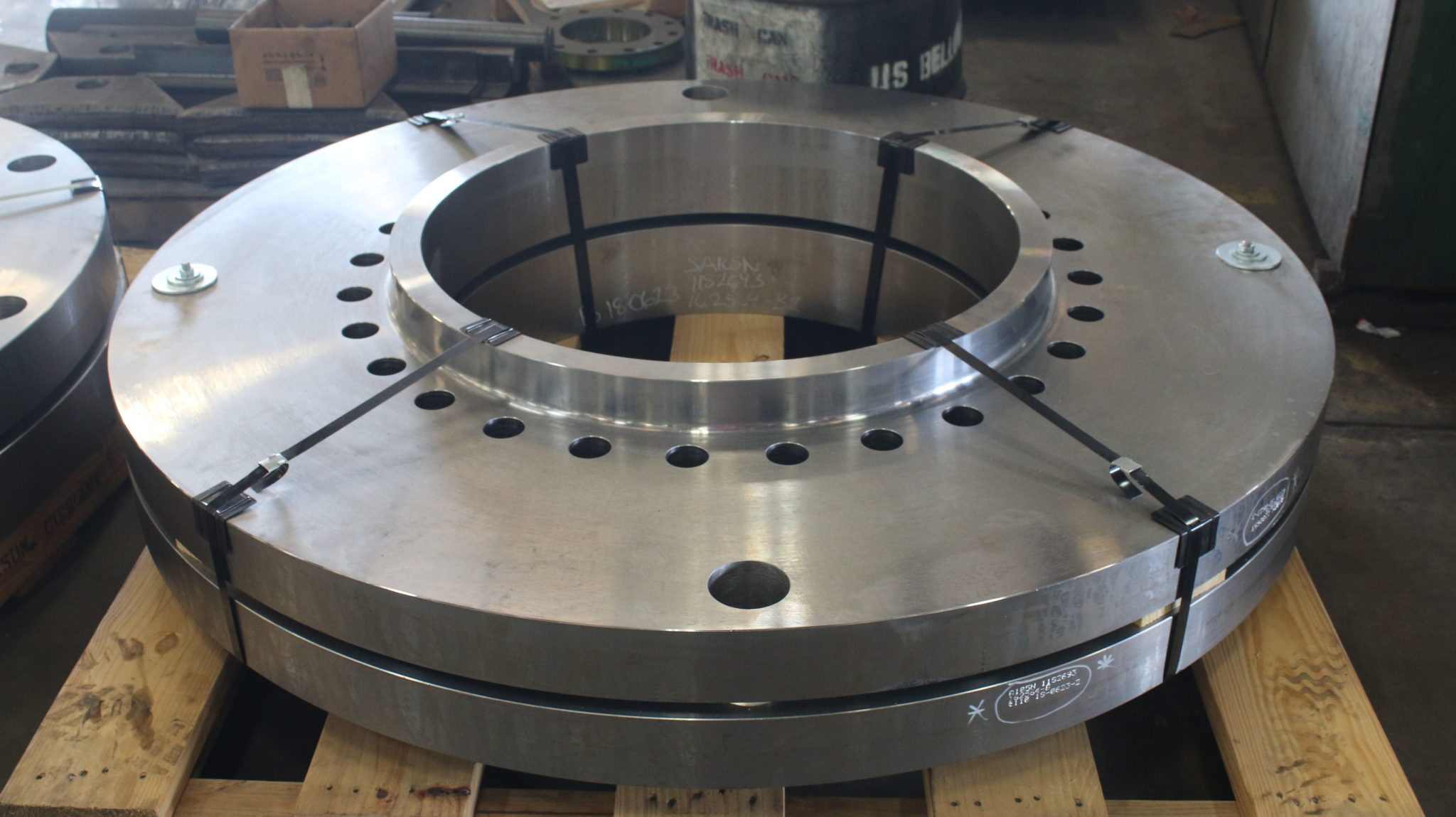
Orifice Flange Unions
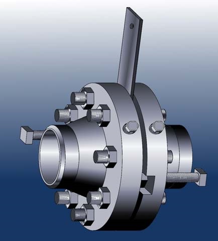
SWECO® Orifice Flange Unions consist of two facing flanges sandwiching a paddle or skillet type orifice plate with flange bolts. Both flanges are equipped with precisely located pressure taps which allow measurement of the pressure drop created by the orifice plate. The precise location of the pressure taps in conjunction with the precisely machined orifice hole allow the pressure drop to be converted to a flow value.
Orifice Flange Unions may be provided as any one of welding neck, slip-on or threaded flanges. Either flat gasket or ring-type gasket designed flange unions are possible.
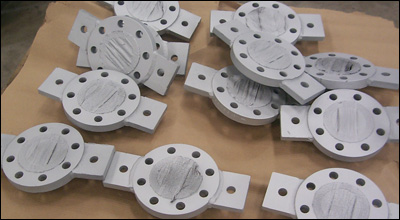
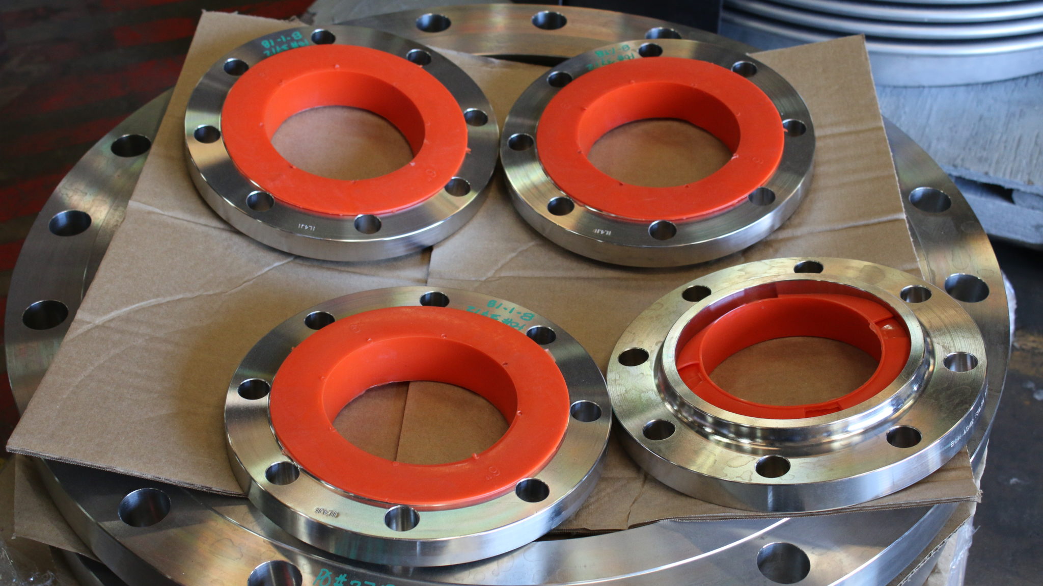
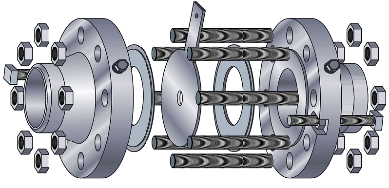
SWECO® Fab Flange Unions are a complete set (as shown) consisting of two flanges, an orifice plate, gaskets, nuts, bolts, and jacking screws.
SWECO® Fab Flange Unions can be made to ASME B16.36, AGA, ISA or your own tolerances and specifications.
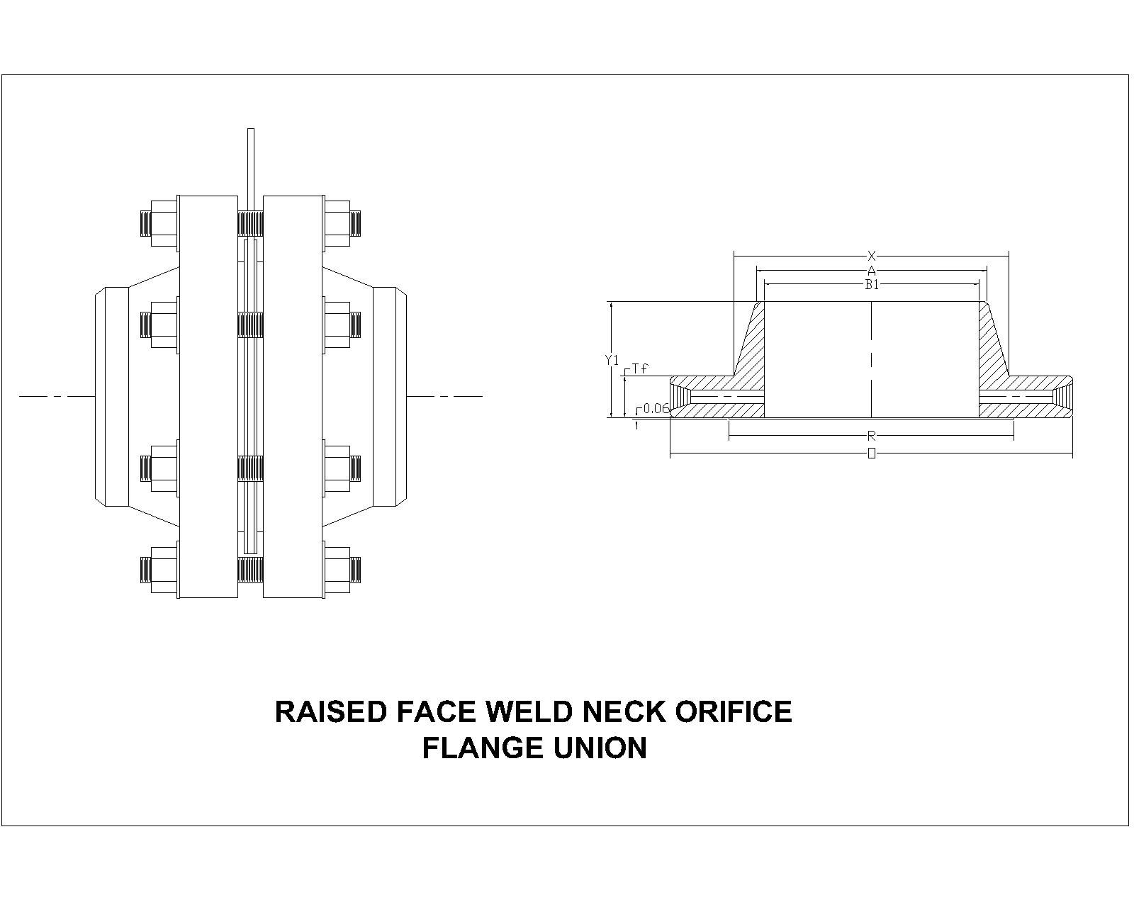
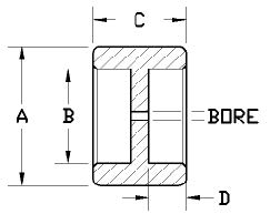
Paddle Type Orifice Plate Installation
SWECO® Paddle Style Orifice Plates (OP) are designed to fit between two specially modified flanges inside what is called an Orifice Flange Union (OFU). Orifice plates within OFUs are designed to create a restriction which causes the pressure of the fluid flowing through the pipe to drop. The drop in pressure varies directly with the flow of the fluid within the system.
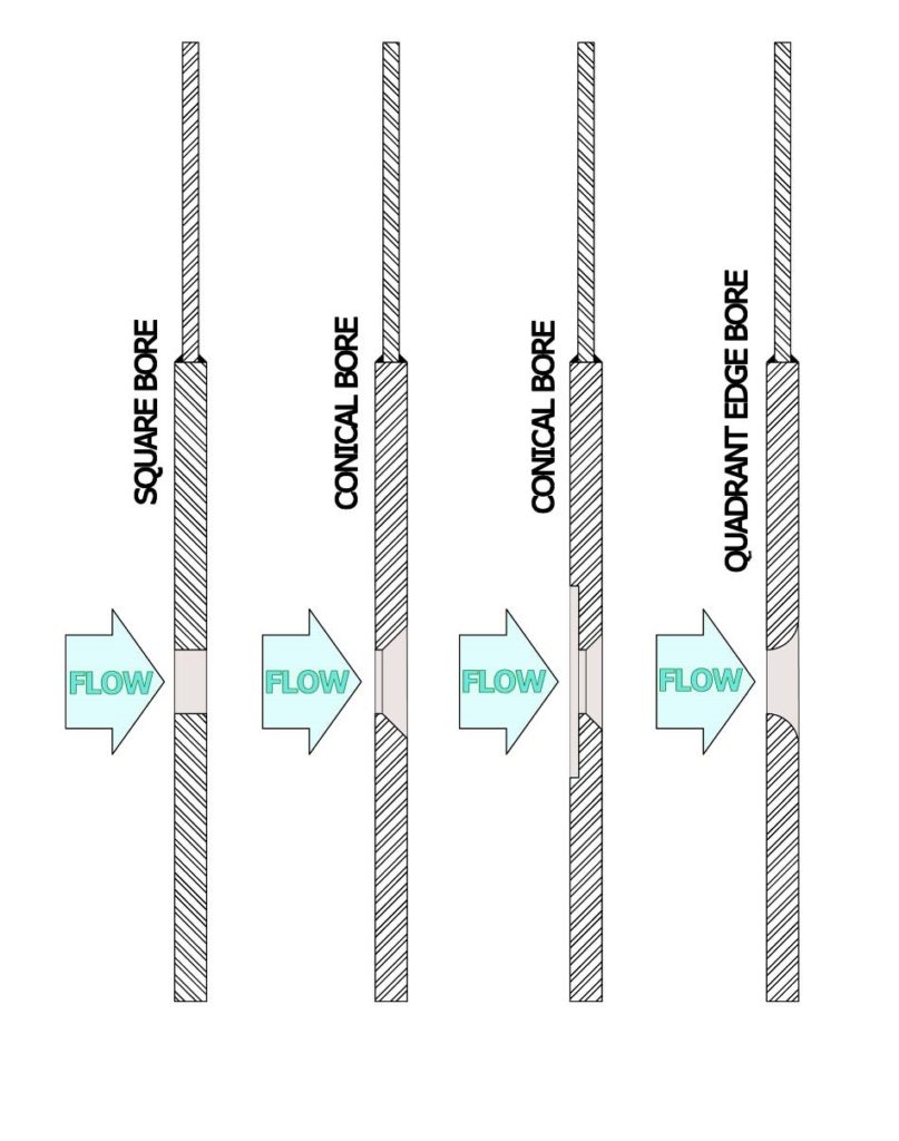
Virtually any bore shape or configuration can be used to measure flow in a pipe, but the most common is a concentric (center) bore with a round hole having square, conical, or quadrant (radius) bore wall. No matter what the type of bore, the square edge goes upstream as shown in the diagram below.
The OFU will consist of the following parts:
1. Two special flanges facing each other (modified with jacking screws and ports).
2. Two gaskets
3. Studs and bolts
4. Your SWECO® Orifice Plate
5. Additionally, some OFUs have dowel pins to improve accuracy of alignment.
It is common for the OFU to have flanges with a material consistent with the pipeline and an Orifice Plate of stainless steel.
To install a new orifice plate in an existing installation refer to the exploded diagram on the next page and follow these steps:
Safety:
You should ensure that all flow to the OFU is blocked and locked out according to company policy. Wear proper Safety Gear.